HVAC - EPA Certification Notes
This page is NOT a complete list of EPA 608 exam notes & content, just the highlights to help recall very specific dates and system classifications.
EPA 608 - Core Exam - Important Points
- The EPA 608 Core Exam defines certification requirements for Type I, II, III or Universal Certification (which is all three) in addition to subjects listed below. Click on each tab for definitions of each type.
- It is the technician's responsibility
to comply with any future changes in the law or EPA
regulations. Regularly visit www.epa.gov for updates
or read industry publications. Also note that
state laws may be more strict than EPA regulations
(but could not enact/enforce laws that are more lenient).
- The most recent update (as of 2026)?
As of 2020, HCFC-22 (R22) and HCFC-142b have been phased out of the US, which means they are curtailing imports & new manufacturing up to the year 2030: which also means you can only get these supplies from recovered or reclaimed refrigerant after that period.
- Reclaimed refrigerant must meet AHRI Standard 700 before it can be resold under EPA regulations (a standard which tests its purity). Also, an owner can only charge their own reclaimed refrigerant back into their own appliance(s) and not others.
- Lastly, used refrigerant can NOT change ownership without being "reclaimed" (under AHRI Standard 700).
- Equipment used to service CFC/HFC/HFO refrigerant must meet EPA Standard 740: such machines must be able to recover multiple types of refrigerants. The exception involves "dessicant dehmidifiers" as they do not use refrigerant.
- A Universal Certification does not cover motor vehicles as that is covered under the EPA Section 609 MVAC certification.
- The EPA Section 608 certification is NOT required
when servicing these HVAC sub-systems:
- External electric circuits; low voltage circuits
- Cleaning condenser/evaporator coils
- Servicing parts that do not involve refrigerant components.
- These are the list of "exempt" refrigerants
& adds that are allowed to be released into
the atmosphere:
- NH3 - Ammonia
- R-744/CO2 - Carbon Dioxide
- Nitrogen mixed with trace refrigerant < 1 oz (for leak detection purposes)
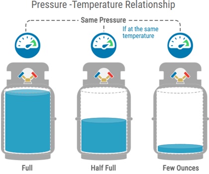
- It is important to realize that under a specific
temperature, pressure will remain the same regardless
of the volume of gas or liquid, as shown in this tank
diagram below. All tanks are at the same temperature,
and therefore at the same pressure each:
* Important: about receiver/accumulator locations
- this subject often tripped me up, but I remember it best by a)
condensing liquid is heavier so it has to "receive"
in the heaviest or lowest part of the HVAC system, which is
in the "bucket" (cannister) right below & after the condenser, so
b) on the "lighter" side, where refrigerant boils into a vapor, there
is less collection as "droplets", which "slowly accumulates"
right before the compressor to avoid liquid slugging.
- The compressor is the heart of the system
pushing hot pressurized gas (thru the discharge line) to
which the condenser is designed to exchange
heat by "rejecting it" to a cooler environment. This
cools the gas into a liquid (hence a condenser) which
is still hot (but less so) and at the same pressure as
it was when it entered the radiator/condenser. Note that
a heavy-duty receiver is typically sitting
behind a condenser to collect & store refrigerant, and
ensure a metering device is alway fed enough liquid.
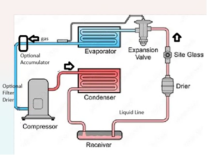
- The core exam tests heavily on the vapor-compression
refrigeration cycle and their components, as listed:
- Receivers- used to collect refrigerant in the off cycle, placed after a condenser.
- King Valve- on the receiver, used to control loss of refrigerant during servicing.
- Liquid-Line Filter Driers- used to collect debris and unwanted moisture from leaks or aging systems--optionally placed on the suction line to do the same.
- Refrigerant Sight Classes- typically right before the metering device to view quality of liquid, can optionally be seen right after the condenser exit-port.
- Liquid Refrigerant Distributors- (not shown) used after metering devices for complex evaporator designs
- Heat Exchangers- used to keep the crankcase of compressor free of liquids during off cycle and prevent slugging.
- Suction-Line Accumulators- see above, as optional on systems, used to also store refrigerant after the evaporator during off cycles, esp. prevalent on colder freezing/lo-temp systems in which unwanted liquid exiting the evaporator is collected and recycled until it can evaporate (to prevent it from entering the condenser)
- Suction-Line Filter Driers- see above, as optional on most systems.
- From the "hot liquid line" the metering device
expands liquid into a gas, which by gas laws BOTH
reduces the pressure and lowers the temp. significantly
into a "flash gas", which enters the evaporator. This
evaporator sits in an air handler
to "absorb heat" from the environment via the air
passing over the coils, and from absorbing the heat
it boils back into a cool gas before it re-enters
the compressor through the "suction line".
Trick Question:the gas exiting an evaporator is "heated" but is still a low pressure, low temperature, but "superheated vapor" before it enters the compressor. Why? The low temp/pressure value is "relative" to gas exiting the compressor.
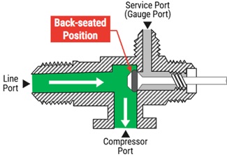
- Service-valves should be understood, the most
important key is to "never front-seat a service valve
when a system is in operation" (which is turning it
clockwise completely to close off access across the
system): they should always be "back seated", as shown:
-
The EPA recommends (but does not require) service-guauges
in which hoses can be manually closed or close automatically to reduce
refrigerant loss while connecting or disconnecting from equipment.
A de-minimus releaseis that in which some refrigerant is lost when disconnecting hoses, and is considered acceptable and not unlawful. -
Your guage manifold and hoses must be pressure-rated to handle the
refrigerant being used --and NOTE that not all manifold systems are
created equally!
- After making a major repair, a system should be dehydrated (remove moisture and other non-condensables) to a minimum of 500 microns, esp. with systems with POE oil that absorb high amounts of water if exposed.
- This is stressed a lot: Under no circumstance should a hermetic
compressor be OPERATED within a deep vacuum: this causes
electric arcing in which terminals inside the compressor can short
and burn out.
- Understand the dates of the Montreal Protocol [Treaty of 1987-89],
followed by the Clean Air Act finalized in 1992,
with several changes in 1995 (R-134a recovery decisions), phasing
out of CFC's by Dec 31, 1995 and fines imposed after 2017 for
each violation:
$44,539 per day, per violation. - Note that the MVAC EPA 609 act imposes a different fine for those infractions: $27,500/day with bounty offerings of $10k.
- The Clean Air Act stresses the following definitions to
understand their reasonings for phasing out CFC's:
- Different refrigerants have different ODP's:
Ozone Depletion Potential - Each free Chlorine atom released by CFC's live in
the stratosphere for 120 years destroying 100,000
ozone molecules each. Ozone (3 oxygen atoms) + Cl reacts
to create:
Chlorine Monoxide + Diatomic Oxygen
The stratosphere is above our living layer (troposphere), which ranges from 7-30 miles above the earth's surface: it contains the most ozone which protects our environment. - CFC's are chloro-floro-hydrocarbons like R11/R12.
- HCFC's are hydro-CFC's like R22/R123 but still harmful.
- More importantly: CFC's & HCFC's do not dissolve or break down in water, so they do not "rain out" of the atmosphere.
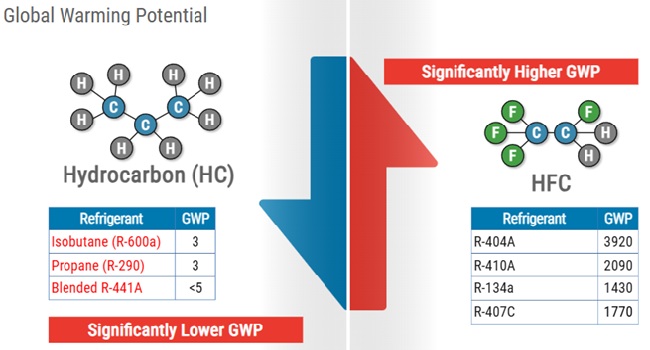
- HFC's have the lowest or no ODP as they have no chlorine,
still still have:
GWP - Global Warming Potential
GWP measurements are compared to carbon-dioxide marked as GWP=1.0 (R-744). HFC's can be in the thousands (see chart).
- Different refrigerants have different ODP's:
- HFO's are hydro-fluoro-olefin's have a small effect on
both ODP and GWP, less flammable than hydrocarbons, but
are still mildly flammable, being in the A2L safety
group, which is diagrammed below.
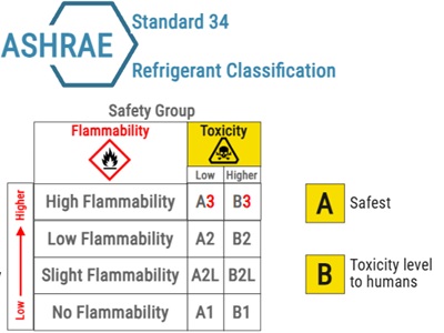
| Flammability | Less Toxic (A's) | Highly Toxic (B's) |
|---|---|---|
| High Flammability
(Hydrocarbons, e.g. HC-290) |
A3 - R50 methane, R290 propane, R600 butane | B3 - Rarely used in modern applications, e.g. R-1140 (vinyl chloride) |
| Med/Low Flammability | A2 - R-152a, R-142b | B2 - R-30 (Dichloromethane) |
| Mild Flammability | A2L - R-32, R-1234yf, R-454A, R-454B, R-452B, R-1234ze(E) | B2L - R-717 (Ammonia) |
| No Flammability | A1 - R-134a, R-410A, R-404A, R-22, R-1234ze(E), R-507 | B1 - R-123, R-124 |
- Azeotropic refrigerants are blends of two
or more refrigerants that have similar properties and
behave like a single substance; therefore, they
only have one pressure-temperature chart and
do not separate into their individual components
during evaporation or condensation.
Examples include R-500 and R-502.
- Zeotropic refrigerants are blends of two
or more refrigerants that have different properties and
behave like a mixture; therefore, they
have multiple pressure-temperature charts and
separate into their individual components
during evaporation or condensation.
Examples include R-404A and R-410A.
They are also called non-azeotropic
refrigerants.
- This complication creates what is called temperature glide, which can range from 1-20 degrees Fahrenheit, and is the temperature difference between the liquid and vapor phases (aka dew-point & bubble-point) of the refrigerant during phase change.
- The bubble-point is the temperature at which the first bubble of vapor forms in a liquid mixture, which is referenced when charging by condenser (liquid line) sub-cooling measurements (for TXV valves).
- The dew-point is the temperature at which the first drop of liquid forms in a vapor mixture, which is referenced when charging by evaporator (suction line) superheat measurements (for fixed orifices).
- R-400 series refrigerants are a family of hydrofluoroolefins (HFOs) that are used as substitutes for HFCs, and are considered near-azeotropic blends, meaning they have a very small temperature glide, typically less than 1 degree Fahrenheit, and behave almost like a single substance during a phase change.
- Important points of near-azeotropic and zeotropic blends:
- These refrigerants leak parts of their components at uneven rates, which eventually changes the percentage of each component and properties of the mixture. This is called fractionation. This happens when a system is consistently topped off without repairing leaks, which can lead to reduced performance and potential damage to the system.
- Proper charging entails pushing liquid through the high-pressure side of the system (condenser) and as a liquid, but when recharging, slowly introduce to the low-side while through the suction line to ensure it enters as a vapor.
- R-410A is a zeotropic blend of R-32 and R-125, with a temperature glide of about 5 degrees Fahrenheit.
- R-404A is a zeotropic blend of R-125, R-143a, and R-134a, with a temperature glide of about 20 degrees Fahrenheit.
- Regarding recovery procedures, be familiar
with these terms and record-keeping standards:
- Recovery of refrigerant is removing it (in any condition) from a system and must be stored in an approved recovery cylinder. From their you can charge it back into the same system or shipping to an approved reclaimer.
- Recycling of refrigerant is using a device to remove oil/impurities via single or multiple passes thru a filter-drier in order to charge it back into the same system (or another system under the same ownership).
- Reclaiming is the reprocessing of
refrigerants under AHRI Standard 700
to meet "virgin product specifications" so it
can be resold to a new owner.
* Important: do not confuse Standard 700 (refrigerants)
          with 740
which is related to Recovery Devices (discussed next).- Self-Contained Recovery Devices - (aka Active Recovery Devices) remove refrigerant without the assistance of components (e.g. compressor) in the HVAC appliance. These must be certified and labeled by an EPA-approved equipment testing org to meet EPA standards (AHRI Standard 740).
- System-Dependent Recovery Devices - (aka Passive Recovery Devices) rely on the compressor or system-pressure of the appliance in order to recover refrigerant.
- AHRI Standard 740 says:
- Recovery devices used with small appliances must be able to recover 90% of the refrigerant when the compressor is working, or reach a 4-inch vacuum.
- If a compressor is not working, the recovery device must recover 80% of the refrigerant using a passive or active process or achieve a 4-inch vacuum.
- Records must be kept on a) type of refrigerant recovered, b) quantity and by type, c) total quantity from DISPOSED appliances per month, d) quantity of refrigerant by type sent for reclamation or destruction.
- Records do NOT require recording the model
and serial number of appliances if they are
designed for
5-50 pounds of refrigerant. - Is is the final person in the disposal chain
that is responsible for ensuring that
appliances containing CFC/HCFC/HFC refrigerant
be disposed of (and evac/recovered) safely.
- Recovery cylinders should be identified by their colors: yellow top and grey body. MOST IMPORTANT: they canot be filled past 80% of their total capacity by weight. This can be controlled by a) a float device, b) an electronic shutoff device, or c) measuring gross weight of the cylinder. Lastly, each cylinder must be free of rust or damage and labeled with the type of refrigerant.
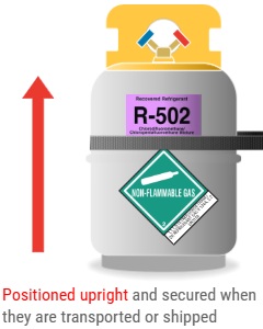
- When shipping recovery cylinders, they must be labeled with a DOT classification tag AND refrigerant label with its type. A shipping form must include number of cylinders of each gas, and shipped w/"hazard class 2.2 Nonflammable Compressed Gas" (image, right)
- Recovery cylinders can NOT be mixed, so separate cylinders are required for each recovered refrigerant. Mixed refrigerants may be impossible to reclaim and may incur an added cost to have them destroyed.
- See this dehydration procedure diagram,
courtesy of the ESCO
Institute:
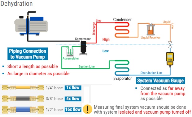
To repeat, dehydration is complete when a vacuum of 500 microns or less is reached and can be maintained more than a few minutes. More on this is discussed here.
Class I Certfication - Main Points
- Type I - allows a tech to work on small appliances that are pre-assembed, pre-charged, & hermetically sealed with 5 lbs or less of refrigerant at the factory. Examples are: water coolers, freezers, window units, de-humidifiers, refrigerators, residential ice machines, and package terminal A/C's.
- Split systems may NOT be serviced by Type I only techs. MVAC (motor vehicles) are also not covered as a Type I appliance.
- Due to small appliance sizing (less than 5lbs of refrigerant), Type I techs can use either passive or active recovery devices (see Core Exam). Note that passive recovery equipment are limited to a maximum charge of 15 lbs of refrigerant.
- Recall from the core exam that the
AHRI Standard 740 says:
- Recovery devices used with small appliances must be able to recover 90% of the refrigerant when the compressor is working, or reach a 4-inch vacuum.
- If a compressor is not working, the recovery device must recover 80% of the refrigerant using a passive or active process or achieve a 4-inch vacuum.
- Super Important: after installing a piercing service valve and the system is already at zero psig (atmospheric), then recovery cannot begin!
- Important to note: if using a passive (system dependent) recovery system, you must access both the high and low side of a small appliance (unless the capillary tube or piston is completed restricted).
- Access to refrigerant recovery in small
appiances is gained by a process stub
or service aperture (gained via a
piercing valve). Do not leave piercing
valves on after repair since they tend
to leak over time.
- New SNAP regulations (via Significant New Alternatives
Program) have approved these refrigerants, but
hydrocarbons can only fit into appliances approved
for use with hydrocarbons only:
- R-290 (propane) - C3H8
- R-600a - isobutane C4H10
- R-450A (58% R134a, 42% R1234ze)
Class II Certification - Main Points
Shortcuts: Recordkeeping -- Recovery Rules
- Type II certification allows work on ANY appliance that is five lbs or more of refrigerant, NOT factory sealed, OR requires recharging--with exclusions of: a) small appliances, b) motor vehicle, or c) low-pressure (type III) appliances.
- For Type II equipment, the EPA separates appliances into two distinct tiers because of how they are handled, listed below, which affects both allowed time to repair, inspect, and retrofit/replace.
| Comfort Cooling | Commerical |
|---|---|
| Includes residential, office, and other occupied commercial buildings. | Appliances used to preserve products sold in retail or in warehouses. |
| Allowed to leak up to 10% per year (by design refrigerant capacity), specifically: R-123 & R-410a systems. | Allowed to leak up to 20% per year, (such as R-22 systems), unless your are a Type III low-pressure industrial appliance (which is 30%). |
For BOTH types, they each follow these rules:
|
|
| A repair deadline can be extended by shutting down the appliance, recovering the refrigerant from and isolated section (or entire) to 0 psig. The appliance does NOT need to be removed from the facility when doing this. | A repair can also be extended to 18 months if charged with an exempt refrigerant but only if an EPA report is applied for. |
| Regardless of appliance type, all appliances must be inspected at least once per year to prove they maintain below their designated leak-rate (10% for comfort cooling, 20% for commerical, and 30% for industrial), unless.. | If the appliance is 500 lbs or more
of refrigerant, it is required to be inspected
and tracked once every three months until
the owner can prove the system has not exceeded
the leak rate for four quaraters in a ROW.
- An exception is granted if there is a leak-monitor installed on the system. |
Section 608 (2019) New Leak Inspection and Record Keeping Requirements
- See table above (last row) on leak-inspection requirements based on if it has 500 lbs of refrigerant as the threshhold for increased leak inspection requirements.
- Records must be maintained for THREE years by the owner/operator (and NOT the servicing company). The servicing company, however, is required to give the owner/operator records or each repair and inspection on completion.
- A serving company IS required to keep records (up to three years) of disposed appliances that are 5-50 lbs of refrigerant (by design).
- Clarification: What must be recorded?
- Type/name of refrigerant
- Quantity of refrigerant added/recovered from disposed equipment in each calendar month.
- Quantity sent for reclamation/destruction, also tracked by type.
- The information can be maintained in either hard copy or electronic format, provided it is accessible for inspection if required.
- You do NOT need to record model & serial numbers.
Section 608 (2019) Rules of Recovery
- Before recovering refrigerant, check the nameplate of the unit for design capacity: if it is above 15 lbs, you can NOT perform a passive/system-dependent recovery per EPA regulations. For passive recovery, refrigerant must be recovered in a non-pressurized container.
- You must always pre-evacuate an empty recovery cylinder before transferring refrigerant to the cylinder (in case of trace amounts remaining).
- To speed up recovery, recover from the liquid line while in liquid phase. After liquid is recovered, continue to evac while in the vapor phase, which is slower. Also, cooling a recovery cylnder can speed up the process (as gas goes from warmer areas to cooler areas of pressure).)
- After recovery, the required levels of evacuation of the system per HVAC Vaccum requirements page - see table below -- to validate no leaks are occuring.
- When recoverying refrigerant from a system suspected of compressor burn-out, watch for signs of oil contamination (it may have a strong odor), and TEST for signs of oil contamination as it may present sludge, acids, etc.
- Recall that a minimum of 500 microns of vacuum needs to be achieved to ensure moisture has boiled out of the system along with other impurities and non-contensables (which is far above the leak-test parameters of 5-10 Hg").
- To counter-act freezing in a system during long vacuum periods, introduce nitrogen to the system to re-condense water-vapor (that is frozen), then restart the vacuum. This is done three times in what's called a "triple-vac process".
Back to Top /\
Class III Certification - Main Points
Shortcuts:
Leak detection --
ASHRAE Standard 15-2013 (alarms) --
Leak repair requirements --
Type III system recovery
- Type III - is work on any
low-pressure system appliance such as a
centrifugal or low-pressure chiller. Types of
low-pressure refrigerant are CFC-11 (now banned),
HCFC-123 (aka R123), HFC-245fa, & HFC-1233zd.
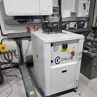
- A purge unit (image, right) separates refrigerant
from non-condensables and moves it back into the evaporator.
It works by suction from the top of condenser on
centrifugal units where non-condensables tend to
accumulate.
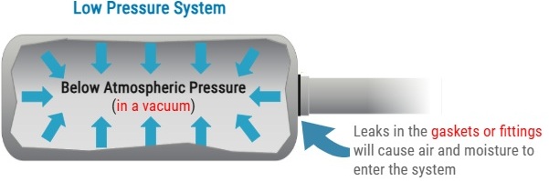
- As low pressure systems operate below
atmospheric pressure, the vacuum pressure will
tend to introduce more air and moisture into
the system than other systems, esp. from aging
gaskets and loose fittings. For this
purpose, chillers require purge units
(image shown) designed to remove air and other
non-condensables regularly.
- Signs of leaking on low-pressure systems may include:
- excessive running of the purge system,
- high head pressure as it runs low on refrigerant and non-condensibles like air/nitrogen increase pressure above its design.
- continuous excessive moisture collection caused by leaks in barrel tubes or condenser, etc.
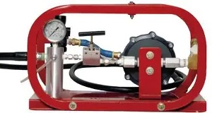
- The most efficient method used to leak-check a low-pressure system is to pressurize the system (with positive pressure) using controlled hot-water circulation or heat-blankets.
- When leak testing a low-pressure centrifugal
chiller with nitrogan, the maximum pressure
needed is 10 psig: any higher
can cause rupture on internal discs/membranes
(which are rated at 15 psig max pressure).
A hydrostatic tube test kit
should be used to detect leaks.
Adding heating blankets or circulated hot water
can be used to more efficiently leak test
these chillers.
- Option 3 is to following the following drainage steps below:
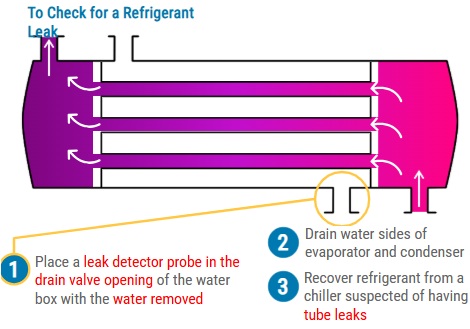
- When chillers are idle, it is best to maintain system pressures above 0 psig to prevent the accumulation of air & moisture in the system.
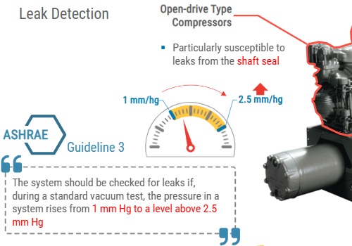
- According to ASHRAE Guideline 3,
the system should be leak-checked whenever a vacuuum
test shows it rises from 1mm Hg to a level above 2.5mm Hg
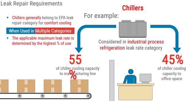
- According to the image below, low-pressure chillers belong to comfort-cooling but if 55% of its capacity is used for industrial refrigeration, it changes its leak category, table repeated below (from core exam guidelines).
Type II & III - leak repair requirements
| Comfort Cooling | Commerical |
|---|---|
| Includes residential, office, and other occupied commercial buildings. | Appliances used to preserve products sold in retail or in warehouses. |
| Allowed to leak up to 10% per year (by design refrigerant capacity), specifically: R-123 & R-410a systems. | Allowed to leak up to 20% per year, (such as R-22 systems), unless your are a Type III low-pressure industrial appliance (which is 30%). |
For BOTH types (including type 3),
they each follow these rules:
|
|
| A repair deadline can be extended by shutting down the appliance, recovering the refrigerant from and isolated section (or entire) to 0 psig. | A repair can also be extended to 18 months if charged with an exempt refrigerant but only if an EPA report is applied for. |
| Regardless of appliance type, all appliances must be inspected at least once per year to prove they maintain below their designated leak-rate (10% for comfort cooling, 20% for commerical, and 30% for industrial), unless.. | If the appliance is 500 lbs or more
of refrigerant, it is required to be inspected
and tracked once every three months until
the owner can prove the system has not exceeded
the leak rate for four quaraters in a ROW.
- An exception is granted if there is a leak-monitor installed on the system. |
- According to ASHRAE Standard 15-2013,
each machinery room must activate an alarm and mechanical
ventilation when the TLV-TWA (Threshold Limit Value -
Time Weighted Average) is exceeded. This
standard is designed to ensure the safety of personnel
by preventing overexposure to refrigerants.
Type III system recovery topics:
- Like a Type II system, for a low-pressure Type III: to counter-act freezing in a system during long vacuum periods, introduce nitrogen to the system to re-condense water-vapor (that is frozen), then restart the vacuum. This is done three times in what's called a "triple-vac process".
- Water recovery systems are also used to recover refrigerant to help prevent water from freezing in the appliance during vacuum.
- When removing refrigerat oil, you need to heat it to 130*F, which releases more refrigerant from the oil at that temperature.
- Recovery & leak-test requirements follow the same rules for both Type II and Type III appliances: see table below (in range of 5-10 Hg").
- IMPORTANT: Before disposing of a low-pressure appliance, the
refrigerant must be recovered/evacuated to at least:
25 mmHg absolute (a)-- which on the [home page vacuum table] is greather than 29 Hg" or 25,000 microns or 25 Torr(a). Recall that 0 psig equals 14.7 psia (absolute) as 14.7 is the amount of atmospheric pressure applied at sea level. - Recovery records for disposed appliances w/5-50 lbs of refrigerant must be kept for three years for any classification of appliance.
| HVAC Type | Vacuum Requirement | Notes |
|---|---|---|
| MVAC/HVAC Default | <= 500 microns or > 29.8" Hg |
Done right before a recharge after repair. |
| Note that numbers below are needed for 'leak testing procedures', while the 500 micron standard refers to what you need to do to 'dehydrate' a system after a major repair. | ||
| Very hi-pressure appliance | 0" Hg or more (atmospheric pressure) | e.g. Nitrogen systems |
|
Hi-pressure < 200lb |
0" Hg or more (atmospheric pressure) | Domestic Type II appliances |
| Hi-pressure
>= 200lb |
**10" Hg+ (< 500k microns) |
Large Type II appliances such as R410a (hi-pressure) |
| Med-pressure < 200lb |
0" Hg or more (atmospheric pressure) | Domestic Type II appliances; does NOT apply to Class I small appliances. |
| Med-pressure
>= 200lb |
**15" Hg+ (< 380k microns) |
Large Type II appliances using R134a (med pressure), etc. |
| **IMPORTANT: Note that ONLY >= 200lb systems have a vacuum requirement of OVER 0" Hg when repairing: high-pressure of 10" Hg and med-pressure of 15" Hg. | ||
|
|
||
A reminder of how "pressure level" refrigerants are classified
via normal operating conditions (104*F in this chart):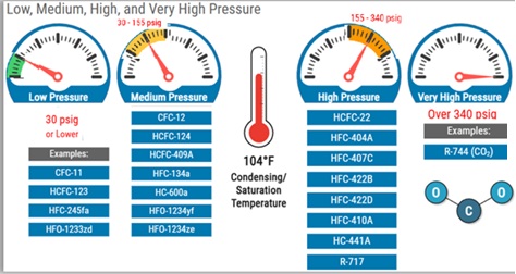
|
||
Contact Me
Orlando, FL 32812USA